Sensorless Observer
Our goal is to design a sensorless observer that works from zero to high speed. In order to do this, we need to understand:
- How motors work
- What an observer even is
- What information we have available
How Motors Work
Structure
There are lots of ways to design a motor, but I’ve found that hub motors tend to follow some key design patterns.
Fundamentally, all motors are comprised of a stator and a rotor.
The stator stays in place, the rotor rotates.
Additionally, hub motors are PMSM1 outrunners2.
The stator is comprised of coils to generate magnetic fields, and the rotor is comprised of permanent magnets with alternating polarity.
There are some more properties I’ve noticed that I don’t have the vocabulary for and will explore later.
PMSM motors are three-phase, which means we output three waveforms to commutate the motor.
Let’s denote these three outputs of our system as $v_u$, $v_v$, and $v_w$.
The structure of the three phases is called a wye configuration.
This means the three phase coils connect at a neutral point.
So if we were to assert $v_u$ and $v_v$ low, and $v_w$ high, current would flow from $v_w$ through $L_w$ split at the neutral point, and flow through $L_u$ and $L_v$ to $v_u$ and $v_v$.
Phase Organization
In real life, no motor only has one set of three phases, there is always a multiple.
There are two ways to organize the coils when doing this:
- Bunch all like-phase coils together
- Interleave phase coils
Option one creates a $1:1$ relationship between electrical rotational velocity and mechanical rotational velocity but has low positional resolution.
Option two creates an $n:1$ (where $n$ is the phase multiple count) relationship between electrical rotational velocity and mechanical rotational velocity which means a full rotation of our output waveform will rotate the motor some fixed proportion of a full rotation. This also, however, gives us higher positional resolution.
To keep things simple, we usually simplify the motor model as just three phases interacting with a single bar magnet. I fell, however, that it is important to understand the real world device because it may be necessary to conduct sensorless observation.
FOC
The modern method of generating waveforms to commutate a motor is called Field Oriented Control (FOC). Let’s break down how it works.
We know we can generate three output waveforms $v_u$, $v_v$, and $v_w$, and we know these waveforms will result in phase currents $i_u$, $i_v$, and $i_w$. But what does any of that have to do with exerting torques?
Well, consider that the three phase currents will combine, resulting in a net virtual magnetic field. The rotor magnetic field will want to align itself with our virtual magnetic field. The stronger our virtual magnetic field, the more force the rotor magnet will exert to align itself.
You may also note, however, that as the rotor approaches the virtual magnetic field, this force will decrease. So it is in our best interest – to maintain a target torque – to rotate our virtual magnetic field to always be orthogonal to the rotor magnetic field, as this would maximuize torque generated per amp expended3.
The Reference Frames
A good way to think of it is as a rotating reference frame. This reference frame is aligned with the rotor, where the axis aligned with the rotor is denoted as the $d$-axis (direct), and the axis orthogonal to the rotor is the $q$-axis (quadrature).
If we have a vector in the $dq$-frame of:
$$ \begin{bmatrix} 0\ 1 \end{bmatrix} $$
This would represent maximum counter-clockwise torque.
This is clearly a desirable reference frame to have, as we can just set this vector to represent the exact kind of torque we want to exert.
But we need to relate this rotating reference frame to the stator to generate the necessary currents. To do this, we’ll make a new stationary reference frame called the $\alpha\beta$-frame.
This frame is fixed to the stator. We use the inverse parke transform to go from $dq$-frame to $\alpha\beta$-frame.
Now, we need to determine our phase currents, which leads us to the final three phase stationary reference frame. Think of it as a coordinate space with three basis vectors, where each basis vector is each phase current.
We use the inverse clarke transform to go from $\alpha\beta$-frame to $uvw$-frame.
This process is also reversable, given three phase currents you can use the clarke and parke transforms to get all the way to the $dq$-frame.
As you may have noticed, bridging the gap between the $\alpha\beta$-frame and $dq$-frame requires knowledge of the rotor’s position.
This, at last, is why an observer is needed.
The Observer
The observer’s job is to estimate the rotor position, to be fed to the FOC loop for commutation.
Normally, sensors can be placed in the motor to get a rough estimate of its position, but these sensors (usually hall sensors) provide low resolution information, and just introduce an additional point of failure.
So where else can we source information that may indicate the rotor position?
Well we know we are outputting phase voltages, resulting in phase currents.
But, we also know that magnets moving by conductors will induce currents in the conductors which produces back EMF. We will find that the shape of the BEMF can uniquely identify the rotor position.
The BEMF is easy to measure at speed because the magnitude of these ripple currents is quite large, but at low speed they are imperceptable.
Some authors propose injecting high frequency noise at low speed, to induce the ripple currents necessary to estimate the rotor position.
The motor has many parameters, which change over time and with temperature.
Many observer methods I’ve seen utilize fundamental electrical equations to build a model for the motor to effectively simulate it to determine the value of these BEMF values at runtime.
They measure specific parameters like the resistance and inductance of the stator in various reference frames, and try to measure the air-gap, yadda yadda using fancy equipment and a lengthy calibration process.
I believe, that parameter estimation could be done at runtime, and we could just give it an arbitrarily large parameter space to use, where it hones in on these “parameters” (they may not directly correspond to real world standard parameters).
We know what a “healthy” current waveform looks like, so we could use that to create our loss function.
By the way, I know this is possible because companies and people have done it, they just don’t have any literature on how they did it.
FOC with space vector modulation open-loop at $\frac{\pi}{80}$ eRads/ms. On the scope, $i_u$ is displayed.

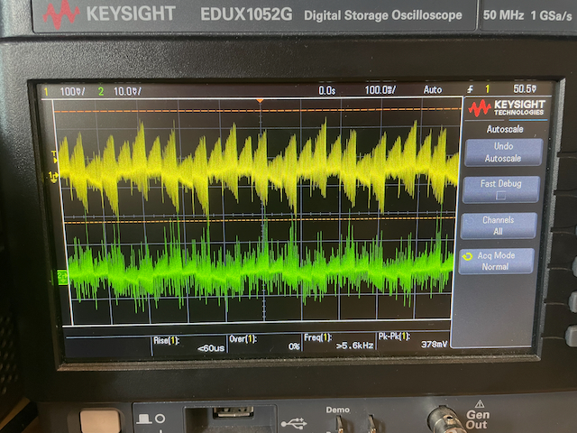
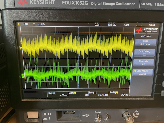
Space vector, trapezoidal, and square modulation resulting $i_u$ and $i_w$ (notice the phase shift of 120 degrees).
Resulting $i_u$ from motor motion when all phases are set low (shorted together).